Low Threshold Acquisition

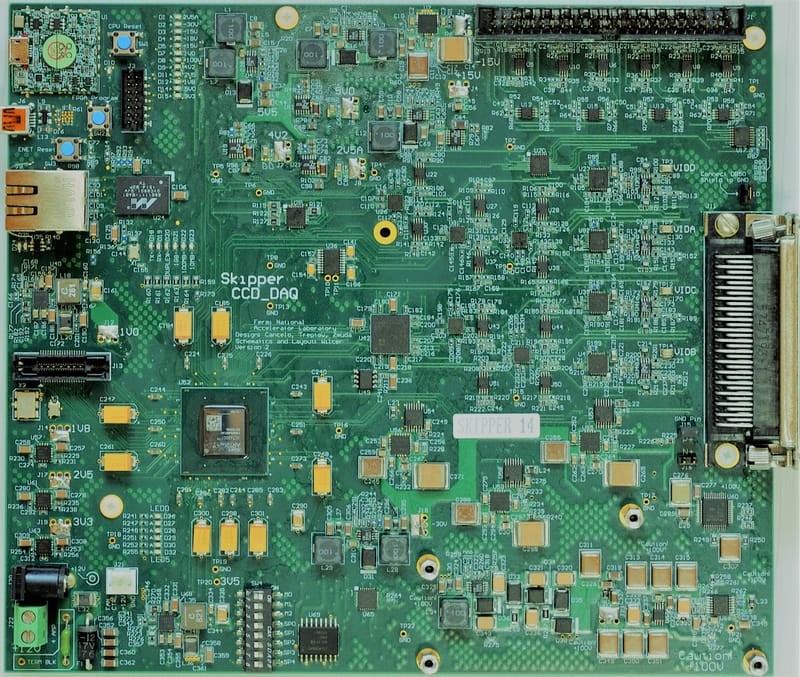
The LTA is a 7X8 inches single printed circuit board for Skipper CCD readout and control with an FPGA as the central processing unit. The CCD requires several DC bias voltages and clocks signals that must be as clean of noise as possible and have the flexibility of being adjusted for performance optimization. A design of this kind requires many DC voltages to power digital and analog components however the LTA only requires an input power source of +12 Volts DC. It connects to the PC through an Ethernet cable. The LTA software runs on the PC and generates images in FITS file format. CCD bias voltages and clocks levels and sequencing can all be controlled by the user, also, the measurements of those levels can be obtained through the on-board telemetry subsystem.
One of the main characteristics of the LTA is its fully-digital signal processing of the video signal generated by the CCD. Instead of implementing analog readouts techniques, the video signal is amplified and connected to a high performance analog to digital converter. The pixel value is computed by the FPGA. This digital characteristic has allowed novel readouts techniques to reduce the noise and/or readout time of the Skipper sensor.
The intrinsic noise of the LTA is much lower than the noise of the CCD which is dominated by its builtin output amplifier, this allows obtaining the maximum performance out of the Skipper sensor. The LTA driving an Skipper sensor has achieved noise levels below 3 electrons when reading the CCD in standard mode (single redout per pixel) and unprecedented deep sub-electron noise of 0.039 electrons by non destructively measuring 5000 times the charge in each pixel.
The LTA has already proven to be the solution for many groups working or willing to work with Skipper-CCDs and will also be part of vIOLETA experiment.